Structure
- Deciding what material to use is a crucial part of making strong and sturdy structure, so you can see the different materials and their properties in the fabrication wiki
Nuts and Bolts
- Fasteners are extremely important in robotics, as they allow you to actually attach different pieces together. Though there are many different types of screws, most teams only use a select few for simplicity and more storage space.
- For American screws, you will see their dimensions written out as: # number – number
- The first number represents the diameter while the second represents the threading
- For example, #4-40 means that the screw has a diameter of 0.112 inches and there are 40 threads per inch
- In some cases, mostly for larger screws, the first number is replaced with the nearest fraction of the diameter of the screw
- This page lists which numbers mean what size
- https://monsterbolts.com/pages/us-screw-sizes
- For Metric screws, you will see their dimensions written out as: M number x number x number
- The first number represents the diameter, the second represents the pitch, and the third represents the length
- For example, M12 x 1.75 x 85 means that the screw has a diameter of 12 millimeters, has a pitch of 1.75, and is 85 millimeters long
- For our team, we, of course, use mostly American screws. The most common we use are #6-32, #8-32, #10-32, and ¼-20
- Below is a table that shows and explains the different types of bolts and gives links to order them (this was taken directly from the NASA
Robotics Alliance Project Robotics Design Guide)
| Screw Type | Description | Photo |
|---|---|---|
| Socket/Cap Head Bolt | Standard go-to bolt, the strongest of all of the socket head, the hex is the hardest socket head to strip out. | 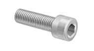 |
| Flat Head/Countersunk Bolt | Is meant to be flush with the material, requires you to countersink the hole. Most standard bolts use an 82° countersink. Most metric bolts use a 90° countersink. | 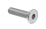 |
| Button Head Bolt | A bolt with a rounded head for areas where a cap head bolt is too large or you don’t want the bolt head to catch on anything. | 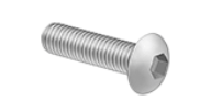 |
| Low Profile Bolt | A bolt with a head that isn’t as tall for use in areas where a cap head bolt is too large. | 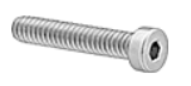 |
| Shoulder Bolt | Bolt with a precision smooth section meant to fit into a bearing or bushing and act as a shaft. | 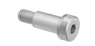 |
| Set Screw/Grub Screw | Screw used to keep something positioned on a shaft or to transmit torque. It is best to avoid these. If they are used, they should only be used to hold axial position on a shaft, not to transmit torque. | 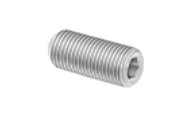 |
Nuts are just as important as fasteners, because without them, these bolts would be virtually useless. Nuts only work with screws with the same threading. So, when using a #8-32 screw, you must use a #8-32 nut. Below is a table that shows and explains the different types of nuts and gives links to order them (this was taken directly from the NASA Robotics Alliance Project Robotics Design Guide)
Nuts are just as important as fasteners, because without them, these bolts would be virtually useless. Nuts only work with screws with the same threading. So, when using a #8-32 screw, you must use a #8-32 nut. Below is a table that shows and explains the different types of nuts and gives links to order them (this was taken directly from the NASA Robotics Alliance Project Robotics Design Guide)
| Nut | Description | Photo |
|---|---|---|
| Lock Nut | Standard go-to nut. Has a nylon insert that prevents the bolt from loosening. | 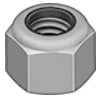 |
| Thin Lock Nut | Used when a standard lock nut is too large. |  |
| Regular Nut | A normal nut, typically only used when creating a “jam nut” where two nuts are tightened against each other on a threaded rod. |  |
| Tee Nut | A type of nut pressed into wood. Sometimes used in bumpers. | 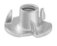 |
| Wing Nut | A type of nut meant to be tightened by hand. Convenient for removing without the use of tools. Can be useful for attaching bumpers. | 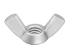 |
| Pem Nut | A nut that is pressed into a part, usually in a part that is too thin to tap well. It’s important to check McMaster for what size the holes the part needs to be for the desired pem nut. | 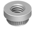 |
| Flush Pem Nut | A pem nut that is used in sheet metal and mounts flush with the material. |  |
| Heat Set Inserts | Used in 3D-printed or other plastic parts. A hole is designed for a specific size listed on McMaster, and then the threaded brass insert is pressed in using a soldering iron. |  |
| Rivnuts | Similar to a pem nut, except it is installed with a specialty tool, similar to a rivet gun. Can be used as an alternative to tapping a hole. Rivnuts are useful for hard-to-reach locations (i.e. box tubing or thin sheet). Rivnuts can be used to provide a semi-permanent nut in a location. |  |
- There are many methods to retain nuts and make sure they do not come off the screw. Next are a few ways to do this.
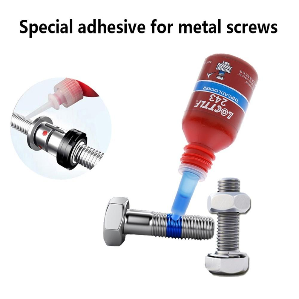
- Loctite:
- Loctite is one of the most common ways to retain nuts. It is a liquid that solidifies on threads and prevents bolts from coming lose from vibrations, which is the most common way bolts come lose on FRC robots. Blue 242 Loctite is used for #8 screws and smaller while Red 262 Loctite is used for #10 screws and larger. For stronger Loctite, the best way to remove the bolt is to heat it up. It is also important to note that Loctite can ruin certain materials, most notably polycarbonate, it touches. Loctite also ruins the nylon on nyloc nuts, so do not use them together.
- As you can see, Loctite is applied to the area that the nut will be
- Loctite:
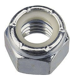
- Nylon Lock Nuts (Nyloc Nuts):
- Nylon lock nuts are lock nuts with a nylon selection the bolt threads into. This makes it tighter and prevents the nuts from becoming loose from vibrations. It is generally agreed that these can be reused. Just remember, do not use them with Loctite.
- The white nylon in the lock nut creates a tighter fit
- Nylon lock nuts are lock nuts with a nylon selection the bolt threads into. This makes it tighter and prevents the nuts from becoming loose from vibrations. It is generally agreed that these can be reused. Just remember, do not use them with Loctite.
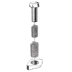
- Lock Heli-Coils (Screw Thread Inserts):
- Locking Heli-coils are inserted into threaded holes and retain bolts and repair broken threading. The hole is tapped with a specific Heli-coil tap, and with a Heli-coil Insert Tool, the insert is threaded into the hole.
- The coil goes around the screw to either tighten it or fix a broken thread
- It is also important to note that fasteners require specific hex key drive sizes and nuts require specific wrench sizes. This page displays the correct tools for different sizes:
- https://monsterbolts.com/pages/us-socket-screw-drive-sizes
Taps and Dies
- Similarly to nuts and bolts, you can also use taps and dies to create threading
- Taps allow you to put threading into a part, so you do not need a nut with the screw. To do this, put a hole in the part that is smaller than the tap (there are specific sizes you should use for different taps). Then, with some sort of lubricant, you screw the tap into the hole. Below is a picture from Custom Part Net that shows this process:
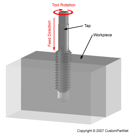
- It is best not to tap a part less than 1/16” thick. If you 1/16” thick part needs to carry a heavy load, you should just use a screw and nut. It is also best to get at least 4 threads into the material, meaning that the depth of your hole varies based on your thread size.
-
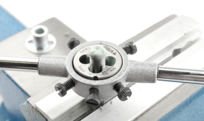
Dies are the opposite of taps. They create threading on the outside of a part, which basically creates your own screw. To do this, you rotate the die around your part. Dies are not used very often in FRC, though. Below is a picture from Threading Tools Guide that shows this process:
-
Also notable, for threaded holes in 3D printed parts, it is best to use heat set inserts. These are brass threaded inserts that are pressed into plastic parts with a soldering iron. There are also inserts that do not need soldering.
Rivets
- Rivets are another type of fastener to connect parts. Rivets are usually used with thinner metal sheets. You can also add rivets to an already connected assembly to strengthen attachments. Blind rivets are a one-time use fastener that only require access to one side of your assembly.
- There are two main parts of a rivet, as seen in the picture below
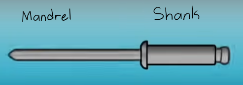
- How the blind rivet works: The head of the mandrel goes first when you put the rivet into the hole. You use a rivet gun to pull the mandrel. As it is pulled, the shank is deformed and creates a sort of head that prevents the rivet from coming out. As you can see, there is also a pre-made tear in the mandrel. This eventually breaks, which allows the rivet to take little room.
- You should not use rivets in places that you are expecting to take apart often. This is because to take out rivets, you must drill them out. Not only can this take longer than a simple nut and bolt, but constant drilling can eventually make the hole too big to use a rivet. However, this can be solved by drilling the holes for the next largest rivet (but you can only do this so many times).
- It is important to use the correct length rivet. If the rivet is too short, the deformation might not be very strong, and if it is too long, then it might not deform enough to hold the parts together.
- Below is a table with rivets sizes and when drill bit to use for them:
| Rivet Size | Drill Bit to Use |
|---|---|
| 1/8” | 30 |
| 5/32” | 20 |
| 3/16” | 11 |
Welding
- Welding is a light, strong, and permanent way of connected pieces, which is why it is usually only used for drivetrains and superstructure. When designing welding parts, it is best to also design some sort of way to hold the parts while they are welded.
- Welding is a big investment for most teams. Along with the cost, welding is highly skill-dependent, and the skill of the welder influences the outcome more than the quality of the materials being used. For this reason, teams often pay sponsors or have experienced mentors to do the welding for them.
- Welding has many things to keep in mind:
- Welded assemblies almost always have some sort of warping, so it is best to design with some tolerance in mind for this.
- When welding enclosed materials like tubing, it is best to include small holes near welds because if not, gasses may get trapped in there.
- Welds can, obviously, break, so you should probably have fail-safe kits with “scab plates” that you can use to reconnect these broken assemblies.
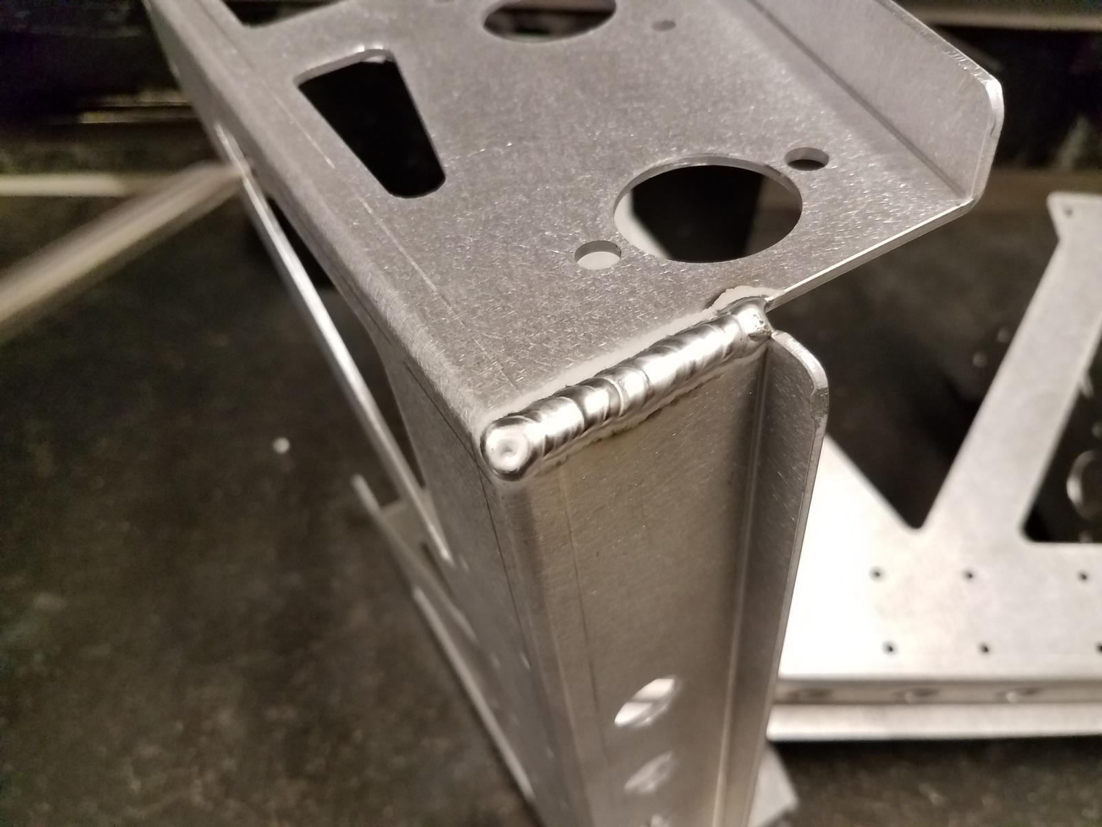
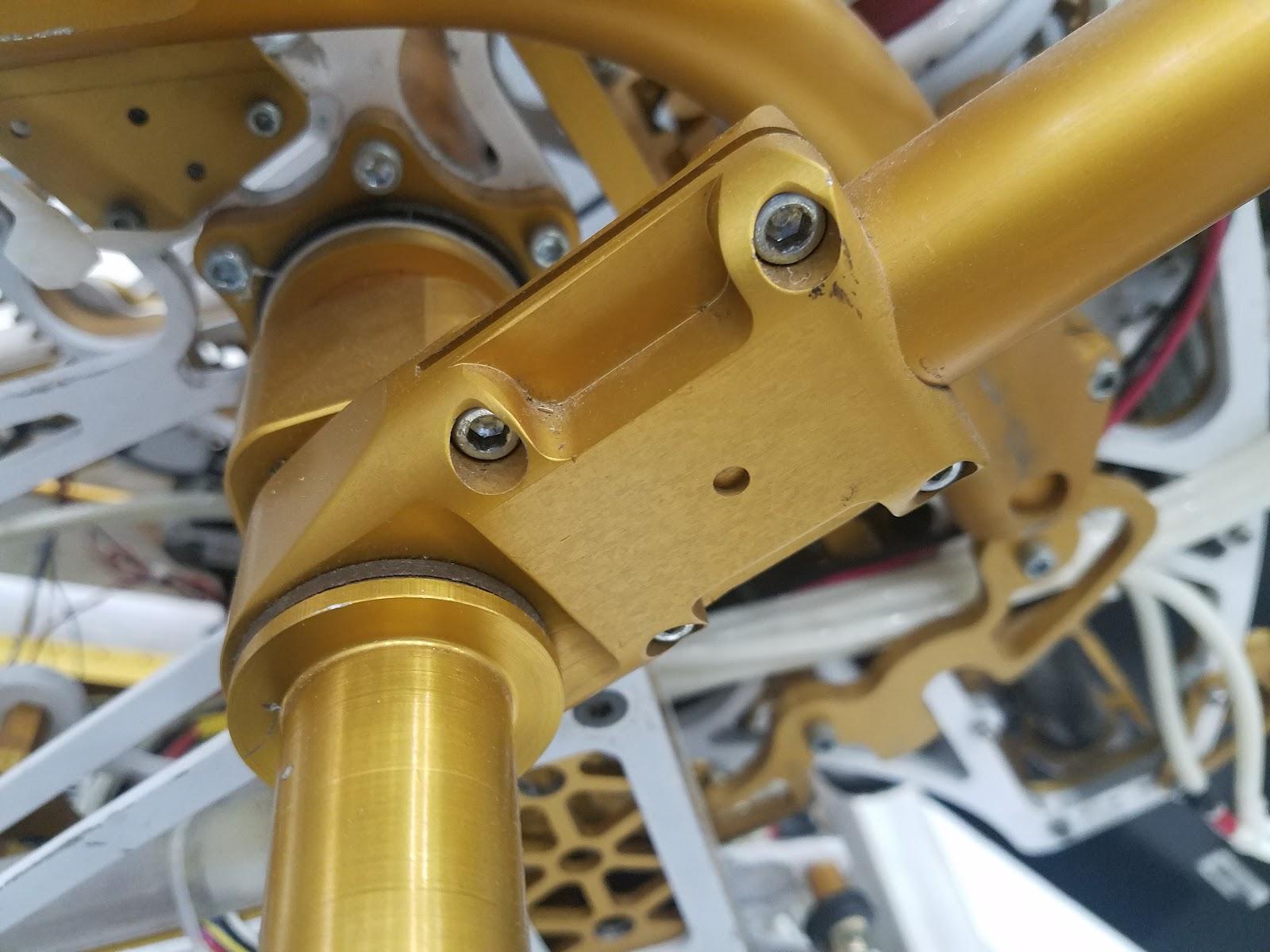
- Welding parts together creates a bump of metal between the pieces. These can be grinded down, but this makes the weld much weaker. It is best to simply keep in mind these bumps when designing. Below is a picture of a corner that was welded for strength done by 95:
Box Tubing
- Box tubing is probably the most used structure in FRC robots. It is a hollow tube with a square or rectangular shape.
- Tubes can be connected with welding, gussets, or connecting blocks.
- 3D Printed Connecting blocks:
- 3D blocks are used to connect tubing. It is especially useful for strengthening a connection between parts that are already welded or have gussets.
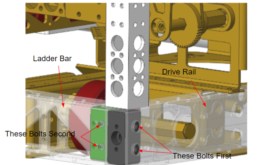
- To use them, you make two that connect to each other. You screw the first block into one of the box tubes. This screw also connects the two 3D printed blocks together. Then, you can attach the second block to the other tube.
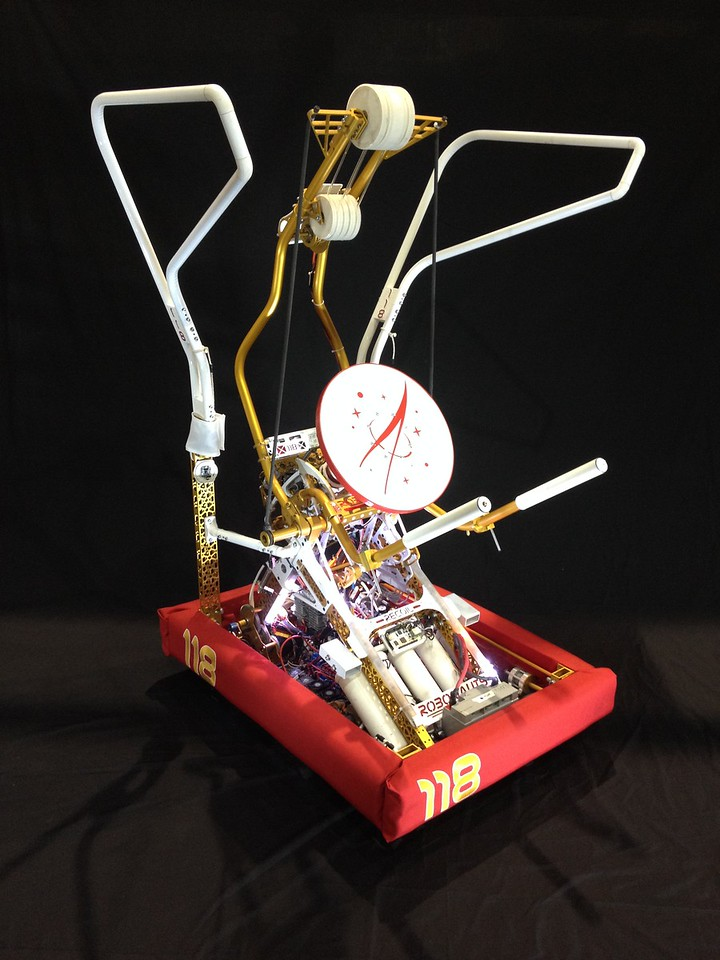
- This picture of 118’s 2017 robot displays a use of 3D printed connecting blocks in a chassis:
- Gussets:
- Gussets are simple, extremely common, and extremely important. The purpose of gussets is to connect two pieces without directly bolting them to each other. This creates clean assemblies and makes it much easier to work with your assemblies.
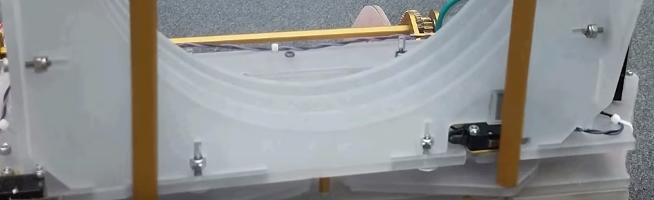
- For example, if you wanted to have two box tubes perpendicular to each other, you could attach them to each other directly like this:
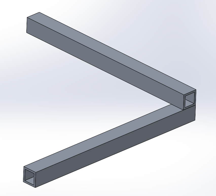
- This, however, can be improved with a gusset (represented by the yellow piece):
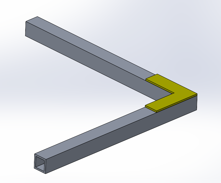
- This makes the assembly look cleaner, but more importantly, it is easier to work with. Designing on a flat and even surface is easier than one that is crowded with bumps. Of course, there will be some cases where you are looking for the structure you see in the first picture. But in many cases, gussets help.
- For example, if you wanted to have two box tubes perpendicular to each other, you could attach them to each other directly like this:
- Gussets are simple, extremely common, and extremely important. The purpose of gussets is to connect two pieces without directly bolting them to each other. This creates clean assemblies and makes it much easier to work with your assemblies.
- Also know that 3D printing blocks and gussets are not ONLY used for box tubing. They are just a common tool for working with box tubing but can be used whenever you find them useful. Do not limit yourself in that way.
Round Tubing
- Round tubing is not as common as box tubing. Again, it is hollow tubing, only this one in a circular shape.
- Compared to box tubing, round tubing is typically around 20% lighter and can be molded into shapes that can prove to be very strong and useful. It also has stronger torsion.
- The downside of round tubing is that it is much harder to machine and design with. The lack of a flat surface makes it difficult to secure anything on it, which can make it a pain to use. For this reason, round tubing is not very common in FRC robots.
- Sometimes, though, this may not be an issue. For example, 118’s 2014 robot use round tubing as a simple way to hold a giant ball:
- Listed below are many effective ways to use/work with round tubing:
- Clamping:
- This attachment method squeezes the tube between two parts to keep it in place.
- A great example is, again, from 118’s 2014 robot:
- Welding:
- Again, as previously mentioned, round tubing can be difficult to work with. When welding, thin walls require skillful precision and are easy to mess up.
- Tube Inserts:
- Similarly to clamps, tube inserts give a place to stick a round tube into. This method is normally used when the tube will not be experiencing high loads or strong impacts.
-
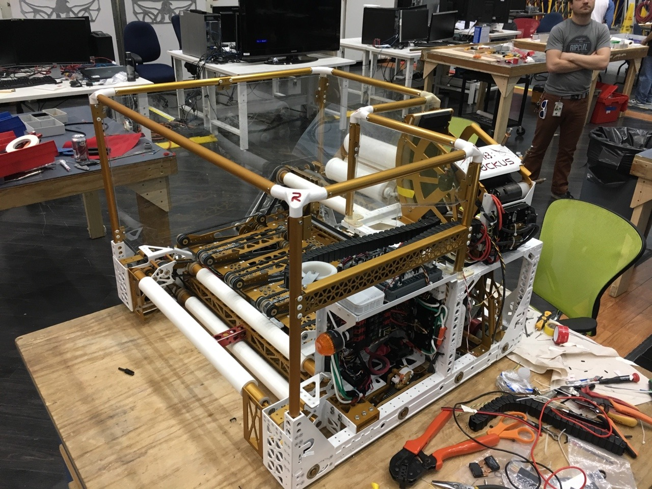
A great example is from 118’s 2017 robot, where the inserts were put in the corners for the tubes, which made up the frame of the robot:
- Rod Ends:
- Rod ends give tubes a practical place to attach to. It also allows to get very specific angles, which makes rod ends perfect for triangle bracing.
- Below is a picture of a rod end:
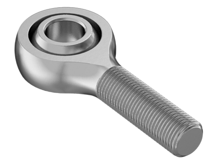
Plate and Standoff Structures
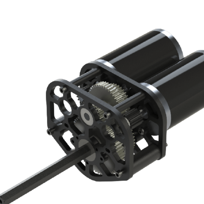
- Standoffs are threaded spacers. When you want to elevate a plate from a certain surface, using standoffs is usually a good option. Doing this creates another plane to build on while also having room under it to add other things. This extra space makes this structure very popular for gearboxes, where the plate can hold the other end of the shaft.
- It is best to use COTs standoffs, as this will take away unnecessary machining time.
- Below is a picture of WCP’s DS gearbox, which uses this plate and standoff method to fit the shafts and gears:
Bent Sheet Metal
- By bending sheets, you can give multiple functions to a single part, which creates simplicity and lightweight.
- The bend radius is the inside radius of a bend. This page shows a table by the Aluminum Association which tells you the best bend radii to use with certain thicknesses: Chart.
- Flange: The flange is the section of a part that you are bending. It is usually the part you put inside a brake to bend it. The length of your flanges should be at least 4 times the part’s thickness, or else the bend will turn out bad.
- Holes should not go close to bends. If you do need a hole near a bend, it is best to have the hole at least 2 times the part thickness away from the bend.
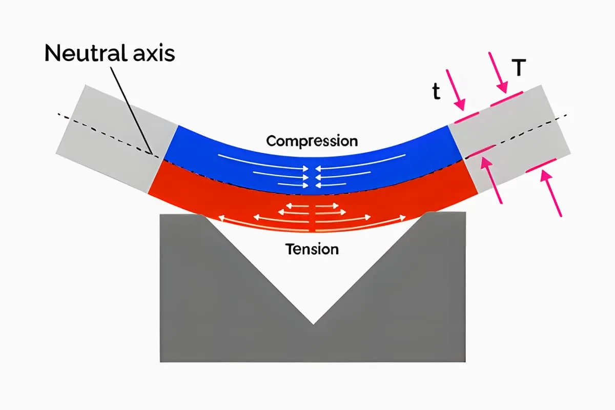
- Bends stretch the outside of the part and shrink the inside of the part. Between these is a line of metal that is not affected. This is called the neutral axis.
- The K-factor is the ratio of the location of the neutral axis (t) to the material’s thickness (T). With this information, you can determine how much the neutral axis has moved from the center, and therefore, how much longer the sheet metal becomes.
Slots and Tabs
- Slots and tabs are a useful way to attach perpendicular parts in an easy and sturdy way. One part has an extrusion while the other part has a slot that fits that extrusion.
-
Also, the part with the extrusion has a screw hole while the part with the slot has a place to hold a nut. This prevents any tapping. Below is an example of this:
- The hole for the screw is a simple clearance hole. The hole for the nut should have a little clearance to make sure it fits
Lightening Patterns
- As previously mentioned, to save weight, teams will sometimes need to add pockets to their parts to make them lighter. These pockets are called lightening holes, and listed next are the different types of lightening patterns:
- Isogrid:
- Isogrid uses 6 equilateral triangles surrounding a circle in the middle. It usually takes longer to machine because of the many pockets. It is important to remember, though, that triangles are the strongest shape. And strength is important especially for lightening holes because pocketing takes away the strength of the part.
-
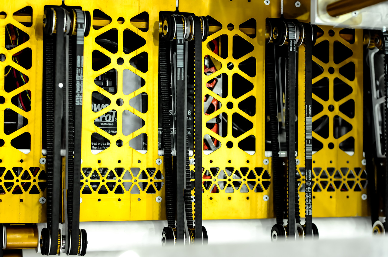
Below is an example of an isogrid on 118’s 2017 robot:
- Triangles:
- Again, triangles are the strongest shape. It is also easy to fit them together neatly in patterns, which takes away a lot of weight.
-
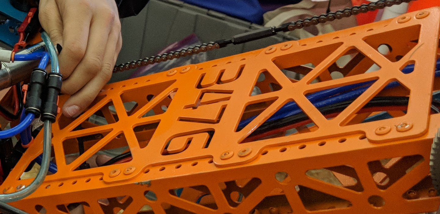
Below is an example of triangle pockets on 3476’s robot:
- Circles:
- Circles are the easiest lightening holes to make, as you can make them with a drill press if you need. Some teams end up drilling holes into their robot when they realize that their finished robot is too heavy.
- Below is an example of circle pockets on 118’s 2013 robot:
- Isogrid:
- Non-Standard and Gearboxes:
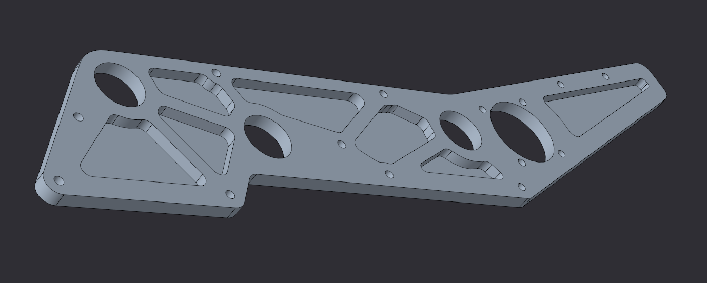
- In many cases, mostly for plates, you will need to make abstract lightening holes. To do this, you take away as much material as possible, but leave struts that connect the bolts, bearings, and other holes on the plate. You must also leave a good amount of material around these holes so that they can handle their load.
- When making the plate, try to put the holes in ways that will form triangles. And when you have a rectangular area that needs pocketing, you can split that into two triangles.
-
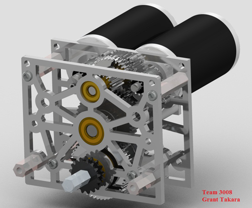
Below is an example of this type of pocketing on a gearbox made by 3008:
- Half-Depth Pocketing:
- You can also create pockets that do not go all the way through the wall of the part. This leaves behind a shell that is around half the weight of what it previously was. You must use caution, though, because it is easy to make this shell too thin and take away all the strength of the part.
- Below is an example of half-depth pocketing from GM0:
Superstructure
- Simply put, superstructure is another above your drive base. It is usually referred to as the structure that you are connecting all your systems to. Superstructures need to be as minimal as possible while still giving good support for everything on the robot.
- Most teams have several people working on the robot’s systems, respectively. This makes communication imperative. Each system needs superstructure to attach to the robot, so there cannot be any clashes between systems looking for structure in the same area. And in a similar way, it is important to make sure that there is no redundancy and to see if certain structures can be used for multiple systems.
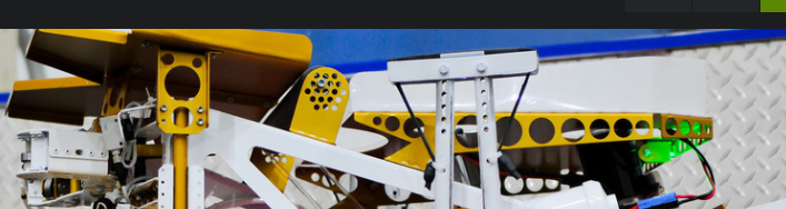
- In the picture below, you can see a robot by 254. The grey metal can be considered part of the superstructure: